

Adding more lumber is the key.
It’s been four years since the Los Angeles City Council passed Ordinance 183893 back in 2015, and since then thousands of apartment buildings have been retrofitted. Since then my team has only retrofitted a handful of buildings in West LA, but I’ve seen over 100 sets of plans to bid on and frankly, some of them do not pass muster. While all of these plans include the use of heavy structural steel, the majority of them do not include the use of diaphragm framing or the addition of lumber to reinforce the existing wood-frame.

Seismic Retrofit Project in West Los Angeles
In this article, I want to cover some technical topics of soft-story retrofitting so that engineers can develop stronger designs and avoid some common pitfalls in our industry. For those of you that don’t have an engineering background, don’t worry I will break things down in laymen’s terms. For those of you that want to read more of my work on soft story retrofitting make sure to visit my website at www.softstoryretrofitpros.com/blog I created this website to be a resource and online learning center for those looking to learn more about seismic retrofits for ‘soft story’ apartment buildings.
‘Principles of Physics’ Approach
For many engineers, architects, and contractors alike soft story retrofitting is a dive into uncharted waters. We need a methodology for making decisions when the correct path is not always clear. In environments with many unknowns, physics ‘first principles’ approach dictates that a hypothesis and methodologies be based developed from the foundations of known truths. In the case of soft-story structures, we should start with the current condition of the building in question. If we do not know the condition of the building’s lumber, how we can determine how much more lumber will need to be added to the building in order to adequately transfer seismic forces to the new structural steel members (moment frames, cantilever column, steel shear walls) that are being installed? This article will cover the lumber aspects of the retrofit. You can see our other soft story articles to learn about steel hardware and connectors.
A mistake that 90% of people make
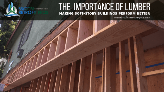
Over 90% of the retrofit projects I have seen get off on the wrong foot – they do not remove stucco before construction. The common mistake is that the stucco is not removed in critical connection sections that would otherwise allow engineers to see the condition of the existing wood members. Engineers, architects, and contracts alike make the mistake of overlooking this simple step. We went through this experience on our very first seismic retrofit project in Los Angeles, we did not remove stucco during the design stage and only removed it once we launched our project. The pictures below illustrate the importance of the designer and contractor to understand the existing site conditions of the buildings’ lumber. This is our soft story project in Harbor City, Los Angles, and it just so happens that this section is where a large plywood diaphragm component is to be installed. As you can see the floor joists have been exposed to years of water damage and the rim joist shows signs of exposure to water over the years. In this case, additional lumber was necessary to create load paths necessary to transfer seismic forces back to the moment frame.

water damaged wood-frame
The original design called for A35 framing angles to the subfloor and 2x lumber blocking for sheathing diaphragm. When you understand that seismic forces will make the floor joists deflect like piano keys under Elton John’s fingers, you realize that more lumber is necessary!

A35 Framing Angles

seismic forces
The forces that the dragline will face are 3 dimensional. The retrofit ordinances and building codes do not require much but an earthquake is a violent force of nature. With that said, the matter requires that we take a serious and extensive look at how to best strengthen the building’s structural wood members. Adding connectors is not enough because the wood will not hold – it will fail. Adding lumber in combination with connectors can help create reliable load transfers. This conversation triggers the question of how much will this cost? I have written other blog articles about cost and you can find them on our BLOG BY CLICKING HERE. The discussion about cost is premature because, without a viable design, a cost is just a hypothetical number. Talking about the cost before opening up the building and assessing what you are working with is baseless. The second trap about discussing price prior to design is that an engineer may start to design towards the cost of construction instead of designing under the purity of math and physics. Of course, the cost is important just don’t let it be the primary factor. Remember that our loyalty in design and construction must be towards the desired outcome, a safer higher performing building!
Below you will see pictures of how much more additional wood was added to the diaphragm section. In some sections, the footprint of the diaphragm was expanded. This is a diaphragm section that I had our carpenters pull out the 2x blocking and replace them with 4x 12” material.

new solid blocking added
Creative Solutions
Ultimately, we installed additional lumber and attached Simpson HSLQ heavy angles along the entire length of the wall. Understand that this section of wall will experience tremendous force during a major earthquake. More lumber tactically placed in this area can make a big difference in the performance of the building. The above pictures represent an additional $6,000 of labor and materials. The tradeoff, you have a predictable load transfer of up to 40+ kips. There are sections of the retrofit that you must add the lumber necessary to add a degree of redundancy and predictable load transfer. Structural Engineers cannot just rely on mathematical assumptions regarding load transfers. The designer must add lumber in certain sections in order to create a higher level of certainty that the loads will transfer to the new steel (SMF, Cantilever column, shear walls) components. Take into account that this can only be done by creating redundancy to the existing transfer paths with the addition of new lumber.

creating a path for seismic forces
Many soft story designs rely on existing subfloors that are assumed to be in acceptable condition. The fact is that seldom is this the case. Existing 1” x 6” diagonal subfloors have often experienced substantial damage over the years. The nails are often rusted or deteriorated by more than 50% and the wood has large knots. These types of subfloors should not be given much value towards load transfer values. Designers should field verify these types of subfloors. When 1 x 6 subfloors are identified, designers should consider a prudent amount of plywood sheathing in the tuck-under parking area. When using shear walls at the perpendicular, consider using 4x horizontal load transfer pathways. Heavy lumber like 4 x 16” lag bolted to floor joist can transfer 27-54 kips along return draglines. It is an easy and less expensive technique that can be done in a smaller footprint.

common frame conditions
Below represents how to install 4x horizontal. The strong walls will then be attached to them and a predictable load transfer can occur. In the scenario, the lumber has a compression strength in excess of 27 kips per bay. This also allows precise 90 degrees alignment with the moment frame.

new framing
Below you can see a technique we used to get tremendous force resistance in a small footprint. Once the floor joist bays are filled in with 4x horizontal, the shear walls go in. This technique helps make it easier to line up the shear panels with the existing column. You can achieve a 40-50 kip transfer path with just 2 bays!

innovative use of Simpson Strong-Wall shear panels
Avoid Charlatans
Back in 2017, I was approached by an engineer that boasted doing hundreds of Soft Story retrofit designs; under the pretense of ‘value engineering’, he bragged and said his designs were efficient and the contractor would not have to shore the building. Let me tell you that when battling earthquake forces, value engineering just means, doing less! Wisdom prevails when prudent measures are taken to evaluate the entire system along the immediate dragline area. I am not talking about opening up other areas of the building that do not fall within the scope of the soft story retrofit. However, if there is evidence of structural deterioration regardless of location. It is prudent to properly verify and evaluate all the connections on the draglines were the retrofits are being done. In this case, the existing concrete pad was only 8” thick in some areas.
ShakeOut Scenario - Los Angeles, Detailed Perspective
Understanding the regional seismology make us better
The USGS has published several papers on earthquake ground motions. A deeper understanding of how the ground will move and which faults are the greatest threats helps shape how engineers create seismic retrofit designs. Dr. Kenneth Hudnut Ph.D at USGS gave a tremendously informative talk at a TownHall Los Angeles event. As part of his presentation, Dr. Hudnut showed us a computer-generated model of ground movement and heat mapping of the forces. It was truly eye-opening to see how much the ground will rise and fall as the seismic waves travel through a region. Watch the video above.
Understand that the dragline will experience violent tension and compression as the S-waves pass through the building. According to the USGS earthquake 'Shake Out' Scenario models, the ground makes experience significant uplift and drop as S-wave travel through the soil and building. It is plausible for the ground to lift and drop 2’- 3’ during the strongest portion of the seismic movement. All foundation members along the dragline should resist force at a prudent level.
Dragline Beam Connection: A New Understanding
Dragline Beam Connection: A new understanding
- This section will receive violent forces and the code is not enough: deal with it!
- Add more lumber, heavier lumber.
- Build redundant transfer load paths with defendable connections on each axis.
- Understand that earthquake may come from one of the following 3 faults. What does this mean for the structure?
It is important to work, with lives and livelihoods of over 250,000 residents at risk. This is serious business with a lot at risk. It is our duty and responsibility to use all of our talent, wisdom, and experience to make these really poorly built buildings perform! It is a challenge that is both noble and worthy. Seldom in our careers do we have the opportunity to engage in such impactful work. Do not be discouraged by the penny pinchers, focus on those that are interested in quality and performance. As Seth Godin would say, “shun the non-believers.” With that said, go to design something amazing today!
